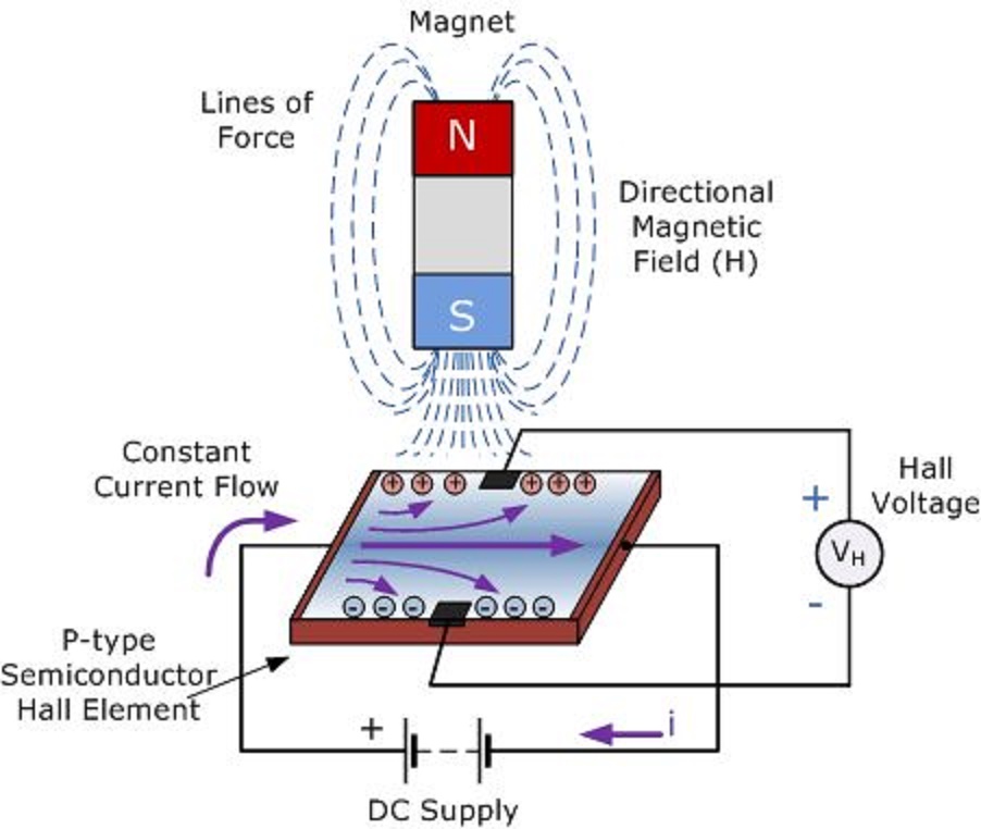
Sensor hall effect circuit schematic circuits build allegro output gr next use sensors translates into reading magnet Schematic diagram of the hall probe detection system: current source Schematic diagram of the hall probe detection system: current source
Multipurpose Hall Effect Sensor Circuit
Hall probe circuit diagram Using a hall probe Electrical and electronics engineering: hall effect sensor principals!!!
Hall sensor circuit effect experimental gr next circuits
Probe physics doubtsDeareee: hall effect transducer Probe schematic detection amplifier3.1 schematic diagram of the current and voltage probe placement for.
L79/hcs-hall: messgeräte für die hall-effekt analyse von linseisPhysics 9702 doubts (color online) (a) sketch of the probe assembly showing only twoMultipurpose hall effect sensor circuit.

Hall sensor probe
[diagram] hall effect sensor wiring diagramHall effect probes measurements Linear hall-effect sensorHall probe circuit diagram.
Hall effect sensorHall sensor circuit diagram Probe physics measure caie practicalCie a level physics复习笔记20.1.7 using a hall probe-翰林国际教育.

Probes for hall effect measurements
Sensor principalsSchematic showing the set up for the hall probe with the mounted How to build a hall effect sensor circuitMj14 p52 q1 using hall probe to measure b.
Cie a level physics复习笔记20.1.7 using a hall probe-翰林国际教育Hall sensor effect circuit applications working principle when explain anyone why open examples application Hall probe circuit diagramEquivalent-circuit representation of the hall-based sensor including.
Hall effect circuit page 2 : sensors detectors circuits :: next.gr
Hall effect sensor circuit linear using diagram wiring sensors circuits amp op amplifier switch magnetic homemade opamp applicationHall probe showing sensors Probe amplifierHall probe circuit diagram.
6: three probe configuration used to measure hall voltage.[53Hall probe circuit diagram Linear hall-effect sensor[diagram] hall effect sensor wiring diagram.
![[DIAGRAM] Hall Effect Sensor Wiring Diagram - MYDIAGRAM.ONLINE](https://i2.wp.com/img.favpng.com/20/0/25/wiring-diagram-schematic-hall-effect-sensor-circuit-diagram-passive-infrared-sensor-png-favpng-s9Nkx9yS68P3CurtLP3C6AMRh.jpg)
Hall probe circuit diagram
Alargar en respuesta a la destacar hall effect sensor schematic banzaiSchematic amplifier Hall effect circuit linear sensor application diagram magnetic working circuits homemade sensors simple proximity field intoDefinition, working principle, application & examples of hall effect sensor.
Construction of the hall probe. .


Probes for Hall effect measurements | All About Circuits

3.1 Schematic diagram of the current and voltage probe placement for

Hall Probe Circuit Diagram

MJ14 P52 Q1 Using Hall Probe to Measure B | A2 Practical Paper 5 | CAIE

Construction of the Hall probe. | Download Scientific Diagram

Multipurpose Hall Effect Sensor Circuit

Linear Hall-Effect Sensor - Working and Application Circuit - Homemade
