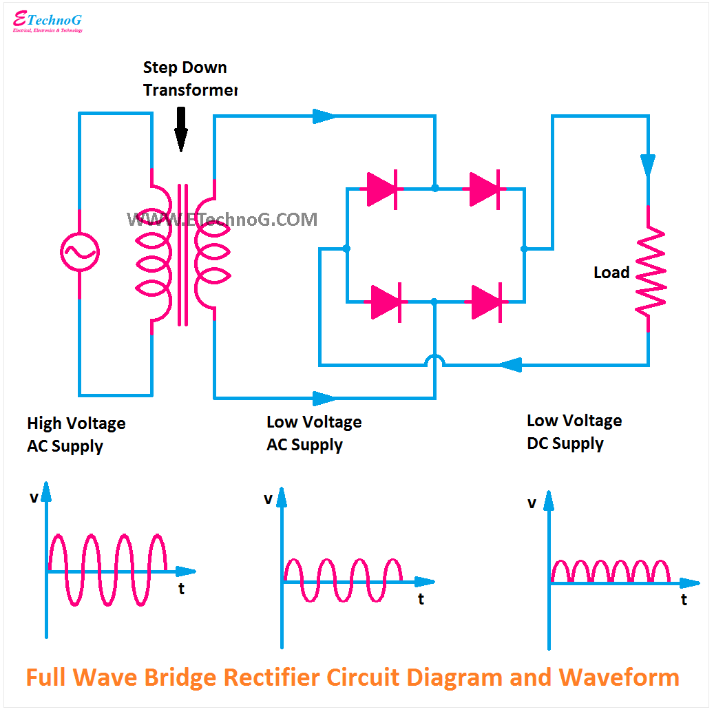
Rectifier circuit waveform input Full wave bridge diagram Rectifier bridge
Explain Full Wave Bridge Rectifier With Diagram Pcb Designs - Riset
Explain full wave bridge rectifier with diagram pcb designs Full wave rectifier circuit working and theory Figure 7: circuit diagram of the full-wave bridge
Full wave bridge rectifier circuit diagram
[diagram] h bridge circuit diagramHalf wave bridge rectifier circuit diagram Full wave bridge circuit diagramDraw the circuit diagram of full wave bridge rectifier.
Full wave bridge circuit diagramFull bridge rectifier circuit diagram Rectifier circuit diagramBridge rectifier circuit diagram with working.

Full wave bridge circuit diagram
What is single phase full wave controlled rectifier? working, circuitFull-wave bridge rectifier circuit Full wave rectifier bridge circuit diagramBridge rectifier circuit, construction, working, and types.
Full wave bridge rectifier circuit diagramBridge full wave rectifier circuit diagram Full wave rectifier schematicBridge full wave rectifier circuit diagram.
Schematic diagram of full-wave bridge rectifier.
.
.

Full Wave Rectifier Bridge Circuit Diagram

Bridge Rectifier Circuit, Construction, Working, and Types
![[DIAGRAM] H Bridge Circuit Diagram - MYDIAGRAM.ONLINE](https://i2.wp.com/www.theorycircuit.com/wp-content/uploads/2018/03/full-wave-bridge-rectifier-circuit-diagram.png)
[DIAGRAM] H Bridge Circuit Diagram - MYDIAGRAM.ONLINE

Full Wave Bridge Circuit Diagram

Explain Full Wave Bridge Rectifier With Diagram Pcb Designs - Riset

Full Wave Bridge Rectifier Circuit Diagram

テスト ヤフオク! - WE 412A FULL WAVE RECTIFIER 1 PCS MINT テスト

voltage - Modified Bridge full wave Rectifier output - Electrical

Full-Wave Bridge Rectifier Circuit